Flash Tube Types

Hi,
I am new to the group and just catching up on old threads so apologies if this is an old topic.

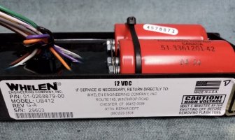
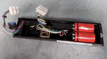
I recent purchased a commander strobe beacon and the pie pan PSU needed new capacitors so decided to upgrade to a UB412 PSU.

I am not that familiar with the flash tubes if I am honest. Will I need a particular spec / capacity tube to suit the UB412 or will it pretty much trigger any tube? Just had visions of it blowing up a lower wattage (if they are measured in watts?) tube up if the trigger is too high - really not sure so any advice would be appreciated.
 
Hi There:
I'm big fan of both the Commander and UB412 PS.

I'm not 100% sure but IIRC, the typical flashtube (S-406) found in 5000 commander is 30 watts. The UB412 is a 90 watt power supply.

I pulled out a UB412, plugged an F-HEAD with an S-406 flashtube in it (same tube found in Commander back in the day), and applied +12VDC to RED wire (power) and YELLOW wire (activate one outlet pair).

Here's what happens:
Because only one outlet pair is activated, the UB412 only drives it at 45 watts which is too much for a 30 watt tube...BUT the UB412 is designed to detect and react to failed flashtubes. Accordingly, after two Comet flashes, the UB412 applied regulation to drive that one tube at about 22+ watts. You can tell the UB412 went into regulation mode because it makes a distinct humming sound at a fixed pitch in regulation-mode (my tin ear tells me it is about a B-flat).

By observation, the first two flashes were over driven as this is when the UB412 tries to detect missing flash tube(s).
This isn't optimal but unlikely to drastically shorten the life of the tube.

Also (according to Whelen's marketing lit when Comet flash was introduced) compared to double-flash, Comet flash is supposedly kinder to the tube because roughly the same energy is delivered in four parts rather than two. IIRC, the primary flash of a Commander was ~18 Joules for double-flash compared to ~8 Joules for Comet flash.

All told, I wouldn't hesitate to use a UB412 to drive a Commander (though I prefer the original dbl flash).

Note: I'm not an authority on this stuff, but I have spent a lot of time tinkering with it.

HTH
 
Thank you so much for the information - really interesting and much appreciated!

Just been looking at the wiring and noticed the unit I purchased has an orange wire but there isn’t any orange on the wiring diagram I found on another thread here. Not sure on the difference?

My flash tube has orange, black and white wires so just trying to figure out which one is cathode, anode and trigger?!
 

Attachments

  • IMG_5474.jpeg
    IMG_5474.jpeg
    107.6 KB · Views: 4
  • IMG_5473.jpeg
    IMG_5473.jpeg
    116.3 KB · Views: 4
  • IMG_5476.jpeg
    IMG_5476.jpeg
    68.7 KB · Views: 1
  • IMG_5475.jpeg
    IMG_5475.jpeg
    153 KB · Views: 4
Me too ... my unit has an orange wire.
From what I see, YELLOW activates ports 1 & 4
Orange activates 2 & 3
Of the four strobe outlets leaving the power supply, looks like mine has hand-written number on each AMP connector:
PORT# WIRE COLORS:
1 BRN/BLK/GRN
2 RED/BKK/BLU
3 ORG/BLK+WHT/VIO
4 YEL/BLK+WHT/GRY

You have one big plug with 12 pins...mine has three four independent 3-pin connectors.

At this point, I'd trust the "IMG_5476.jpg" you have.

I don't have the part numbers handy bug I definately ordered the right 12-pin male/female AMP connectors from digikey in the past.

Where you say, "My flash tube has orange, black and white wires" -- I'd "assume":
BLK is CATHODE/GND
ORG is ANODE (should measure ~+500VDC relative to GND)
WHT trigger wire.

If you're not clear on what the trigger wire does, google "understanding xenon trigger transformer" and make sure you understand it...others explain it 100 times better than I can.

BOTTOM LINE: you _don't_ want to confuse your trigger wire with your anode wire!

HTH
 
Last edited:
Sorry for the delay! I had to fight my computers to offer this:1773258491898.png
Port#1 is out of view as it is connected to the F-HEAD (and still flashing!)
Might not be helpful but this _is_ my UB412 as I purchased it (these port numbers were hand-written when I received it).

Based on the date-codes stamps on the big red capacitors:
Yours: "04-34" - made in the 34th week of 2004
Mine: "02-51" - made in the 51st week of 2002

When you get it working...I'd love to see some vids!

Keep us posted!
 
Last edited:

Forum Statistics

Threads
56,105
Messages
457,950
Members
20,360
Latest member
Bpems597