Whelen How does the Rota-Beam Commander work? Reverse motor polarity?

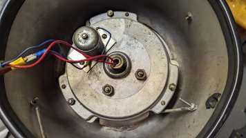
The rota-beam command oscillates 205°, the perfect amount to display 3 of the beacon's 4 bulbs. But how does it oscillate? It seems like the travel is too far for a standard cam / arm mechanism like the 174. I think it reverses motor polarity.

I noticed a few things;
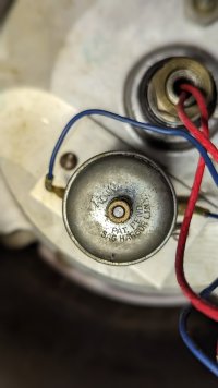
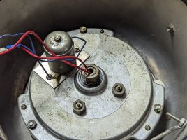
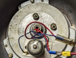
  • The motor and light itself have no required polarity. You must ground one wire and then power the other.
  • The motor reverses if you reverse the polarity.
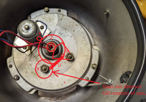
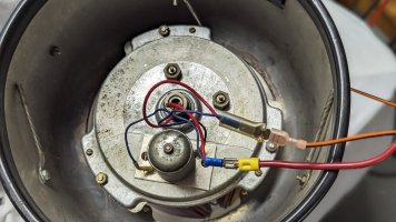
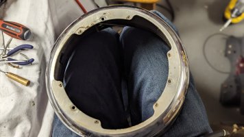
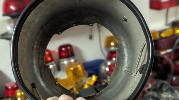
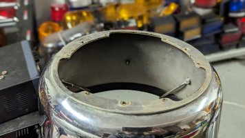
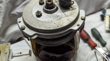
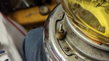
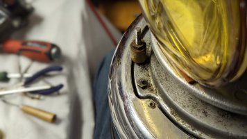
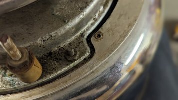
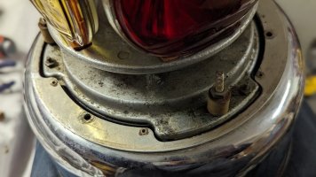
  • There are two lugs on the bottom that seem to correspond with stop points of oscillation.
So I assume the beacon simply reverses polarity in some way by having a contact on the mechanism hit these lugs/contacts. There must be some sort of buffer in there in the gears or a clutch type mechanism to keep the abrupt stop from damaging things.


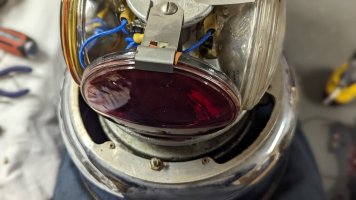
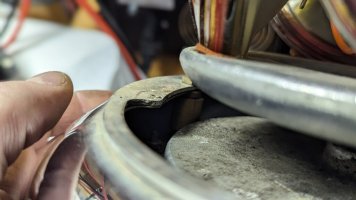
PXL_20221230_124906058.PORTRAIT.jpgPXL_20221230_124901100.jpgPXL_20221230_124923416.PORTRAIT.jpgPXL_20221230_124940167.PORTRAIT.jpg

Here is a video of it running

174 mechanism, not at all similar.
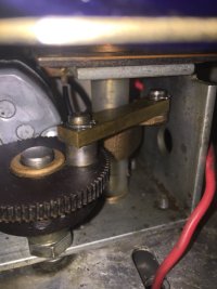
174.JPG

And if you are curious about Rowe motor company... well here is what happened to them. Superfund site! https://cumulis.epa.gov/supercpad/SiteProfiles/index.cfm?fuseaction=second.Cleanup&id=0202330
 
Last edited:
John, I believe that I have seen electric motors that reverse direction when they incur resistance or obstruction. There are 2 points of obstruction. I wonder if it is as simple as that?
 
John, I believe that I have seen electric motors that reverse direction when they incur resistance or obstruction. There are 2 points of obstruction. I wonder if it is as simple as that?
It very well could be, I don't want to open it. The fact that reversing polarity changes direction makes me think there is more of a polarity reverse by making contact with these, but who knows. I am not opening up what is what I believe to be the last one left.

Video
 
Last edited:
  • Like
Reactions: OliverD and Lt.214
It would be interesting to know the how, but given the rarity of surviving examples, I would not open it.
 
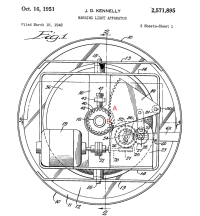
Honestly, I can't picture how this mechanism is present in your Rota-Beam Commander, but it shows that, depending of the ratio of gears A and B, you could have more than 180 degrees of rotation within the swings of oscillation:

1672501545783.png

If polarity was responsible for the motion, then I'd expect more wires/terminals/wiring. Looks to me like the blue wires go right to the motor, and that the motor is mounted on a plate (as an assembly) that's screwed on to the surface of the mechanism.
Further, it looks to me from the vid that the motion slows down, stops, but when it begins to move in the opposite direction, it jerks forward as if something already in motion is "catching"...like there's still a cam (with a little wear-and-tear).
Not even worth $0.02 -- just my $0.0075.
 
Fascinating light! IDK, curiosity has often gotten the best of me…and I have survived. I would be concerned about the noise that light is making, like something is/about to be loose or broken internally.

Any light/motor will reverse with polarity…so long as it doesn’t conflict with the vehicle’s electric system (we had a ‘61 IH pumper that was positive ground, thus the 17 on the roof rotated in reverse).

The lugs seem too far apart for stops. If 12 o’clock is 0 degrees, 205 degrees would be about 7 o’clock…unless there are rubber stops/cushions internally. The lugs appear to be about 270 degrees.

I may be the sole voice of abandon, but I would start by taking a peak under the motor and I would have multiple video cameras recording everything! I tried searching the Patent Office for a diagram of the oscillation works, but I could only come up with with the quick disconnect mount (Whalen + oscillation) Perhaps someone else can have better luck..
 
  • Like
Reactions: RS485
:) Could we possibly pitch in to pay to have it X-rayed?

Here's what I picture:
1672508657603.png

"Y" is a gear on the shaft of the motor. It's mechanically connected to gear "Z" which is mounted on the main center shaft via bearing such that it rotates freely around it. "Z" is mechanically connected to gear "X" which has the cam bolted onto it but "X"s shaft doesn't go all the way through to the other side. This allows cam "U" to rotate 360. Cam "U" connects to gear "V" which affects back-and-forth movement of gear "W" of the center shaft, similar to the patent diagram I pointed to above.
Sorry for the crappy drawing but hopefully it makes some sense.
 
Last edited:
Hmmm…very interesting! I could see that working.

I’m willing to pitch in on an x-ray! I’m not at all familiar with the assembly of a Rota-Beam but I would bet it’s not that difficult to remove the bulb cage and then remove the works from the base (I could rebuild a 174 in my sleep). My guess is the works case splits in half (screws next to the bolts that secure it to the base) and all the works are accessible.
 
Last edited:
  • Like
Reactions: RS485
:) Could we possibly pitch in to pay to have it X-rayed?

Here's what I picture:
View attachment 241919

"Y" is a gear on the shaft of the motor. It's mechanically connected to gear "Z" which is mounted on the main center shaft via bearing such that it rotates freely around it. "Z" is mechanically connected to gear "X" which has the cam bolted onto it but "X"s shaft doesn't go all the way through to the other side. This allows cam "U" to rotate 360. Cam "U" connects to gear "V" which affects back-and-forth movement of gear "W" of the center shaft, similar to the patent diagram I pointed to above.
Sorry for the crappy drawing but hopefully it makes some sense.
I am going to meter the motor and see if the polarity reverses. If not, I assume that it is similar to the noted design. I have looked at some designs in the aircraft industry which were oscillating and came out around the time of this light. My assumption is their similar if the polarity is not the method. I should be able to put a meter to it tomorrow.
 
  • Like
Reactions: Maxim2Eng and RS485
I am going to meter the motor and see if the polarity reverses. If not, I assume that it is similar to the noted design. I have looked at some designs in the aircraft industry which were oscillating and came out around the time of this light. My assumption is their similar if the polarity is not the method. I should be able to put a meter to it tomorrow.
Assuming the two blue wires connected to the motor, also go directly to the two input wires (orange, red?) that you connect to in the vid, I don't see how you can measure anything other than the polarity of how you connected it.
_IF_ there's some strange/cool mojo going on to manipulate polarity to affect direction, you'd have to get _inside_ somewhere to measure and observe it. Do I have that right or am I missing/assuming something inaccurately? Do the two blue wire connected to the motor, connect directly to the two leads you twiddle in the vid?
I was going to see if the amp draw changes at any point. That's true, I was going to meter the bulb contacts, and the two lugs protruding through the base. I am curious why polarity doesn't matter, I wanted to see what changing the input did to the bulbs, base, etc. Then I was going to separate the bulb wires and motor wires and poke around at the bulb contacts. You raise a good point, if there is goofy polarity stuff it would be out of reach
 
The more I think about it, the less I like the idea of polarity reversal, especially on the fly. To isolate polarity reversal from the vehicle system, the motor would have to be totally isolated from the frame/works/vehicle. SignalStat did this on the later iterations of the DualComm so the passenger side rotators could counter rotate from the other side by adding rubber bushings between the motor/gear box and the bulb frame. Even then, the power to the motor is always the same, just reversed so it runs in reverse. It doesn’t appear the Whelen motor is so isolated.
 
Last edited:
The more I think about it, the less I like the idea of polarity reversal, especially on the fly. To isolate polarity reversal from the vehicle system, the motor would have to be totally isolated from the frame/works/vehicle. SignalStat did this on the later iterations of the DualComm so the passenger side rotators could counter rotate from the other side by adding rubber bushings between the motor/gear box and the bulb frame. Even then, the power to the motor is always the same, just reversed so it runs in reverse. It doesn’t appear the Whelen motor is so isolated.
Yeah, I think it is mechanical. Some good points were raised. Thanks guys. I had a hard time wrapping my head around the mechanism, but good points were raised. I also found it odd that there is no base/housing ground. It seems unusual wiring, but I don't think it is the reverse mechanism. Thanks for the input everyone.
 
So reverse polarity is out, but check out this possible first mounting method. The gearbox twists into the base of the light. It looks like this was abandoned and the standoffs used. This may explain why the light sits so low in the skirt with plenty of dome room at the top.

Normal
PXL_20230117_235521077.PORTRAIT.jpgPXL_20230117_235512472.PORTRAIT.jpgrotoh.jpg

taken apart
PXL_20230118_000027566.PORTRAIT.jpgPXL_20230118_000101884.PORTRAIT.jpg
PXL_20230118_000109852.PORTRAIT.jpg
PXL_20230118_000046215.PORTRAIT.jpg

Sitting in a higher "twist in" position. If I loosened the top and bottom portions of the gearbox it would rotate and clamp onto the protruding tabs.
PXL_20230117_235955136.PORTRAIT.jpgPXL_20230117_235952789.PORTRAIT.jpgPXL_20230117_235949940.PORTRAIT.jpgPXL_20230117_235940385.PORTRAIT.jpg
 
Perhaps the twist-lock method was dropped in the Commander because of the back-and-forth motion of the lamps... It seems like eventually it would work itself loose and drop out of the frame, versus a lamp assembly that turns only in one direction (the locking direction).
 
Is it possible the shape of the base and mech were just designed so you could remove the mech for servicing while leaving the base bolted in to the vehicle? I.e the twist-lock-ish shape was just coincidental, not intentional?
 
  • Like
Reactions: stansdds
Is it possible the shape of the base and mech were just designed so you could remove the mech for servicing while leaving the base bolted in to the vehicle? I.e the twist-lock-ish shape was just coincidental, not intentional?
It could be, and that was my first thought. But it doesn't fit through well at all. Much larger slots would have made more sense for that. The way the space in the mechanism locks onto the tabs seems pretty convenient. I also noted the height fits the dome better. I doubt they were released this way, I just wonder if it was the first plan and the movement made it not work. The motors on 80h gear boxes secure into the mechanism with tabs like this too. I am scared to loosen the gear box enough to let it lock in place in the commander, but it is interesting.
 
Last edited:
  • Like
Reactions: RS485
For those of you who are still interested. ...


Well........... I popped the motor off and put the borescope inside. If I was going to have one of the things I was using break, I'm glad it was the borescope and not the light. The the scope wouldn't record and light portion of the scope failed so I have a phone video of the screen of the scope, which is not good quality..... but...

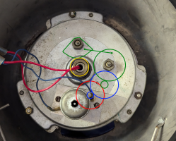
I saw the internals... it's a bit confusing because there are way more gears than "external studs"


The "studs" that I thought looked like electrical contacts are only for the linkage gears as they are suspended with only one point of contact to allow the linkage arm to swing; hence the more substantial contact points.
png intern.png


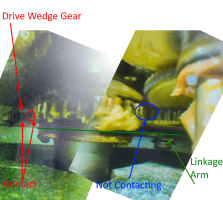
This is the bit that had me confused. There is no contact at the blue point, the drive point is the red circle.
drive.png


So @RS485 was very close when he made the drawing above. It's a similar to my oscillating aircraft light (which isn't Whelen actually) with a linkage and a "wedge" gear. That makes sense because Whelen was doing a lot with aviation when this light came out.

 
Last edited:

Forum Statistics

Threads
54,372
Messages
451,526
Members
19,307
Latest member
schmal