Federal Signal Super Beacon Ray Model 174

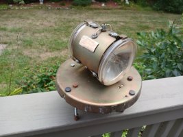
Info based on serial # 1N11P9
6 VDC
December 1959

However I think it has been upgraded to 12V (as it looks like it says 12V on the motor), has 2 lights, plastic amber dome.

I would like to test it and wonder how to wire it up. I have a non functioning variable DC unit I need to fix first.

Does the positive DC supply go to the red crimped wire? And where does the negative DC supply attach?

Any other recommendations, warnings, etc, appreciated.

Thank you

20240829_094003.jpg

20240829_094007.jpg
20240829_094039.jpg
20240829_094200.jpg
 

Attachments

  • 20240829_090826.jpg
    20240829_090826.jpg
    121.8 KB · Views: 14
A Beacon Ray gets its connection to ground via the three sections of threaded rod running through three holes drilled into the roof of the car it's mounted atop.
 
I wired it up as seen in photo. Ground to one of the three bolts. However I have a short between + and ground and seeing the current spike quickly as I dial up the DC supply.

Disconnected everything and I see 12 ohms resistance between the motor terminal and ground, and under 1 ohms resistance between the lamps wire and ground.

Any thoughts? Thank you, Mark

20240830_121013.jpg
 
Sounds like you have a short to ground somewhwere.

The Beacon has two 12VDC circuits and two individual 12VDC loads;

#1) The 12V Motor and;
#2) The two 30W VDC Sealed Beams

The Motor is direct wired from the 12VDC In to the Light;

The Sealed Beams are powered via a "Brush and Energized INSULATED Rotating Shaft" (for lack of a better description).

I'd first put a 15A DC fuse between the light and your Power Supply. Shunting a PS to ground is bad ju-ju...

I'd check the isolation between the two circuits and ground.

I'd disconnect the 12V + going to the motor then reconnect 12V + to the Bulbs only to see if the two Sealed Beams Light up. If both Light up Circuit #2 is OK, If you blow your imput fuse there's a short to ground in that circuit.

Then repeat powering the Motor only, (if the motor pins Circuit #1 is OK)

If no joy, start tracing the circuit starting from the Bulbs.

PS I don't remember seeing that Cotter Pin looking thing at the 12V light's connection . Bad Repair Maybe? Anyone?
 
If I did my math correctly, 1 ohm at 12 volts produces 144 watts, provided 12 amps are available. This measurement makes sense for a beacon with four 35-watt sealed beam bulbs.

However, your beacon does not match the tag on the skirt. I see that your beacon has only two bulbs. Take them out and test them individually with your power supply. If they are marked with any bulb number, we can interpret that and tell you their wattage and calculate their current requirements individually.
 
  • Like
Reactions: QUICKONE
Here's what a new Beacon's electrical connections look like from the bottom

1725051723537.jpeg
 
It looks like Fiberboard is partially missing/repaired and the 12VDC feed to the Brush via insulated copper twisted wire might be touching the Chassis and making it to Ground. Maybe??

Now I know how a Surgeon using a DiVinci robotic to opertate remotely feels like..lol
 
It looks like Fiberboard is partially missing/repaired and the 12VDC feed to the Brush via insulated copper twisted wire might be touching the Chassis and making it to Ground. Maybe??

Now I know how a Surgeon using a DiVinci robotic to opertate remotely feels like..lol
I see what you mean. The wire may be touching the rivet, will check that out. Yes the fiberboard is snapped off, I have the missing piece but that section seems useless.

Thank you
 
So I think I am using the wrong DC supply for this testing. My supply is only good for 1 amp at 12V.

I have another supply but not variable that is 13.6 V fixed at 12 amps. But this one would need a fuse wired up.

The bulb I pulled is GE 4446 12V.

20240831_114147.jpg 20240831_114202.jpg
20240831_114224.jpg20240831_114654.jpg
 
A 4446 sealed beam is a 25-watt PAR36 flood bulb. The Model 17 would benefit from spot bulbs instead of flood bulbs.

As your Model 17 has a plastic lens, you would be wise to use 4416 sealed beam bulbs, which are 30-watt PAR36 spot bulbs. If your Model 17 had a glass lens, you could use 4464 sealed beams, which are 60-watt PAR36 spot bulbs.
 
The 4416 is the correct bulb for the Beacon Ray, it is a 30 watt bulb. To operate a 12 volt Model 17 you will need a power supply that can provide a bare minimum of 6 amps continuous power and it will likely take a few extra amps to get the motor started.
 
Understanding more. I loosened the fiberboard and realized it houses a brush that runs along the shaft. If I move the brush away from the shaft I have no continuity to ground.

Loosening the fiberboard and placing a plastic guitar pick underneath it moved the needle on continuity to ground. Odd that it was in the hundreds of ohms but finally settled around 8 ohms. I think the contact of the brush to spindle messes with the readings. I sprayed electrical cleaner on the brush and shaft.

So with isolated circuits I read 8 ohms to ground on the bulbs and 18 ohms on the motor.

Do these readings seem right?

I thought I had some 12V auto fuses but cannot find any. I have lots of 250V glass fuses. I will need to buy some fuses and rig up a fuse holder. What is the recommended fuse value for this beacon? If I need 6 amp to run it,,10 amp?

Thank you

20240901_111156.jpg
 
It sounds like you found your Shunt to Ground (with the stranded wire right before Brush Assy)

Btw, When tracing the old VDC circuits I wouldn't focus too much on the Ohm readings because you're working on an "Old" DC motor and Sealed Beam Elements that will never meter out the same, (due to age, wear, voltage loss and corrosion).

I'd focus on proving Continuity or Non Continuity, (for both Positive and Negative circuits).
 

Forum Statistics

Threads
54,612
Messages
452,486
Members
19,444
Latest member
jebenstock