Fire Department Alerting System

mpaine

Senior Member
Member
Dec 20, 2011
732
46
USA
Gentlemen (and ladies),
 
For your consideration, I've constructed this in-house department alerting system. Now, I understand this isn't a vehicle install per-se, however I thought it might be interesting to do a write-up on it since I know it is an interesting topic among firehouses. The build consists of old fire alarm speakers, fire alarm bells and Feniex Apollos (Red/Blue). This system was created merely from scratch out of a parts bin and has evolved into an extremely efficient alerting system. 
 
The speaker visual devices were hand painted black and assembled. We chose black because, obviously, it covered up the word FIRE and changed the color from red, so that the public, should they be visiting our station, would not confuse it with the building fire alarm system. We have 5 speaker visuals total. One is located in the bay of the Rescue Engine, the second is located in the bay of the Tower Ladder, the third is located in the first out Engine's bay, the fourth is located in the back workroom or shop, and the fifth is located in our training room/lounge. The speakers are connected to a Uniden BCT15X and broadcast a constant fire/police scan group, however are interrupted by the Motorola Minitor pager, and will then broadcast the tones and voice page.
 
The bells were originally planned to accompany the speaker visuals at every location, however they are louder than we first thought, so we put two up. One at each end of the station. There are plans to add a second bell between the workshop and the lounge, however it is still in the works. The bells sound for 4 seconds after the pager alerts, which is slightly longer than our pagers will normally beep for on alert.
 
A disconnect switch was mounted by the main office, which allows the system to be bypassed, or reset in the case of a false Minitor trip, or a "Test" page. The system is highly expandable, and uses a series of timer relays to control it's operation, driven off of a Motorola Minitor pager amplified charger, which, as most of us know, contains its own internal relay.
 
This has been an extremely fun project to do. I am willing to answer any questions about it's technical details. Please feel free to comment/criticize.

Inhouse 005.jpg

Inhouse 001.jpg

Inhouse 002.jpg

Inhouse 003.jpg

Inhouse 004.jpg
 
Last edited by a moderator:
Pretty simple, really. The bells and the visuals are powered off of two Altronix 6062 timer relays. (http://www.amazon.com/gp/aw/d/B003XA8HU4?pc_redir=1404834753&robot_redir=1). All you need after that are two power supplies. One low amp (500ma or less) 12 volt supply for the relay trip between the timers and the minitor amp, and another higher amp supply depending on what you're using for notification.
 
Very cool. Definitely something different on here. Before I left my previous department a few years ago we had strobes put-in in the day room and the workout room. The strobes were hooked up to the town pager system so when our tones went off it triggered the strobes.
 
Can you describe how the pager trips the alarm relay? Is there a dry set of contacts on the pager?
 
Looks great. How exactly did you set it up so that the minitor would trip the system?


Also, just a thought...have you considered seeing if you could wire it to flash blue for EMS calls & red for fire? A department that I did ridetime with for paramedic school had a FedSig system that had a visual warning device attached to the overhead speaker (it flashed blue if an EMS vehicle was dispatched, red if an engine was dispatched, & yellow is a heavy rescue or ladder was on the call; if multiple units were assigned, then they'd flash multiple colors). I'm sure it was a super pricey system, but I liked looking up and seeing what type of call was about to be dispatched.


PS, full pics & videos of all aforementioned apparatus must be posted next
 
Last edited by a moderator:
  • Like
Reactions: Doug
Can you describe how the pager trips the alarm relay? Is there a dry set of contacts on the pager?
That is correct. There are a small set of low amperage dry contacts inside the pager base. They are accessed via the accessory port on the back.

Looks great. How exactly did you set it up so that the minitor would trip the system?


Also, just a thought...have you considered seeing if you could wire it to flash blue for EMS calls & red for fire? A department that I did ridetime with for paramedic school had a FedSig system that had a visual warning device attached to the overhead speaker (it flashed blue if an EMS vehicle was dispatched, red if an engine was dispatched, & yellow is a heavy rescue or ladder was on the call; if multiple units were assigned, then they'd flash multiple colors). I'm sure it was a super pricey system, but I liked looking up and seeing what type of call was about to be dispatched.


PS, full pics & videos of all aforementioned apparatus must be posted next
That would be awesome! The way our county works, there's one set of tones for each department. So it doesn't matter what type of run it is, it's always the same set of tones. It's a great idea, but we would have to have a different set of tones for Fire and EMS, two pagers, and another set of relays. Easy enough to be done, just not possible due to the way the county dispatch is set up.

Plus it probably doesn't help that my department does not run EMS. Haha.
 
I'm trying to get something almost exactly like this done myself. I'm just not technically sound. May have a couple guys on my dept who are able to do stuff like this message you on here so we can get something like this done, if that's ok.

Quick sidenote, doe this mean that the system will not alert if there is not a pager in the amp base?
 
That is correct. You'd have to have a pager in the base to make the relay contacts close and alert the system.


And of course it's okay if they message me! My email is mpaine@cetroniafire.org.
 
Last edited by a moderator:
That is correct. You'd have to have a pager in the base to make the relay contacts close and alert the system.


And of course it's okay if they message me! My email is mpaine@cetroniafire.org.
That's exactly what we need because we don't always have people at the station. One stay overnight for storm details or periods of time we know we'll be busy. Tornado weather, winter storms, busy town events, etc.

I'll see who I can tell to get ahold of you/
 
That's exactly what we need because we don't always have people at the station. One stay overnight for storm details or periods of time we know we'll be busy. Tornado weather, winter storms, busy town events, etc.

I'll see who I can tell to get ahold of you/
As do we! And alright, let me know. Thanks.
 
That is correct. There are a small set of low amperage dry contacts inside the pager base. They are accessed via the accessory port on the back.
Did you have to cut into the base and solder or was it simpler? What model Minitor did you use?

I am very interested in this, may look into doing something similar in our station.


Just did a little poking around and found this over on Batlabs...


As far as the charging base for the Minitor II goes, the Service manual part number is 68P81106C79 for Minitor II NLN3041A (110VAC) NLN3042A (220VAC)and NLN3044A(12VDC)


The NRN3041A NRN3042A and NRN3044A models include a relay that is energized whenever an alert is received, and a six-pin DIN accessory connector located on the rear of the unit. The six-pin mating plug supplied with these models may be wired to provide the following external functions:


Remote Speaker Audio (Pins 1 & 6)


An external four-ohm speaker may be connected


to the charger/amplifier via pin 1 (audio) and


pin 6 (ground return) of the plug, to provide both


remote speaker audio and internal speaker audio


at the same time.


Relay Dry Contact Closure (Pins 2 & 3)


When the accessory relay is energized, its contacts


close and present a short across pins 2 and 3 of the


connector. The relay contacts are rated for 10 watts,


maximum at 28 volts dc/ac rms. Within the limits of


the 10 watt rating, the closed contacts will handle up


to 750 milliamperes continuously and will switch up to


400 milliamperes of current.


Relay Closure Timing Control (Pins 4 & 5)


Pins 4 and 5 of the accessory connector are used to


select the time duration of the relay contact closure.


If these two pins are NOT used (open circuit), the relay


will remain energized for approximately 10 seconds after


an alert is received. If pins 4 & 5 are SHORTED, the relay


will remain energized until the 'RESET' button on the front


of the charger/amplifier is depressed. Pressing the


'RESET' button causes the contacts to open and turns off


the ALERT indicator."
 
Last edited by a moderator:
Did you have to cut into the base and solder or was it simpler? What model Minitor did you use?


I am very interested in this, may look into doing something similar in our station.
No, I did no cutting into the base. I actually used a MIDI cable and connected it to the accessory port which enabled me to make use of the relay. 
 
  • Like
Reactions: SirenWorld.com
The MIDI cable is the easiest way to get those ports available for accessory use.   You can get them at online for dirt cheap.

I love this idea... and with the dual color F6 heads you definetly could to a red for fire/blue for ambulance set up since the lights have multiple modes.  If they're individually triggered by separate tones, you'd need a base and a pager for each separate monitored tone set.

Now... get me someone with a Cannon in there, and do three modes - Red Fire, Blue EMS, and Alternating RB for dual response! 
 
  • Like
Reactions: mpaine
Did you have to cut into the base and solder or was it simpler? What model Minitor did you use?
The connector for the external connections is built in to the charger-amplifier. Here's a link to the manual that comes with the Minitor V charger/amp: https://drive.google.com/file/d/0BxAVX2o_3yDlaEV3ZFJFVzg3OGc/edit?usp=sharing

It has pics and info on the accessory socket and the relays.

This is why the Minitor has been the radio of choice for station alerting systems for many years for those on tight budgets.
 
The MIDI cable is the easiest way to get those ports available for accessory use.   You can get them at online for dirt cheap.


I love this idea... and with the dual color F6 heads you definetly could to a red for fire/blue for ambulance set up since the lights have multiple modes.  If they're individually triggered by separate tones, you'd need a base and a pager for each separate monitored tone set.


Now... get me someone with a Cannon in there, and do three modes - Red Fire, Blue EMS, and Alternating RB for dual response! 
Thanks very much for you positive comments. It definitely means a lot to hear a lot of positive feedback and praise, especially when its something that you've built with your very own hands. 

But cannons were my first choice, however the 180 degree light spread of the Apollo was just too inviting! And either I'd just need two pagers and bases or a PC with two relay boards and a tone decoder program.
 
  • Like
Reactions: SirenWorld.com
Myself and a few other guys on my department have been trying to get a system like this set up for awhile. We just cant get all of the technical stuff worked out, I will definitely be in touch!

Awesome set up btw.

Also, could you by chance post pictures of the "control board" or how the electronics are set up?

Thanks.
 
Last edited by a moderator:
Myself and a few other guys on my department have been trying to get a system like this set up for awhile. We just cant get all of the technical stuff worked out, I will definitely be in touch!


Awesome set up btw.


Also, could you by chance post pictures of the "control board" or how the electronics are set up?


Thanks.
I am working on this for someone else as well. I will make it public when I can get to it! I'll see if I can mock up a wiring diagram as well.
 
That's a great setup. I'm not great at making something like this but would love to make one. Is there a step by step on how you got it all setup or where can I go to make one similar to this?
 
I did something similar using a $35 Raspberry Pi connected to a scanner.  It can close different contacts based on tones too.
 
Last edited by a moderator:
Just so everyone knows I haven't forgotten about this. I am just working on currently getting this system to interface with our road signs. Even though my department is all volunteer, we have a good deal of staffing on hand most of the time, so we came up with the idea to interface the in-house system with the flashing "Emergency Vehicle Entrance" signs down the road at either end of the station. Once I get this area settled, I will post wiring diagrams and full layouts of how the system works and how you can make your own. Thanks for all the interest!
 
Just so everyone knows I haven't forgotten about this. I am just working on currently getting this system to interface with our road signs. Even though my department is all volunteer, we have a good deal of staffing on hand most of the time, so we came up with the idea to interface the in-house system with the flashing "Emergency Vehicle Entrance" signs down the road at either end of the station. Once I get this area settled, I will post wiring diagrams and full layouts of how the system works and how you can make your own. Thanks for all the interest!
Not to be "that guy," but were you able to get the details on paper for us?  I have been tasked with setting up a simple in station alert system.  Just looking to have 2 apollos, and maybe an audible alert if it were simple enough.  I have been doing some digging, and it looked like the easiest setup includes a motorola Minitor and amplified base charger ran to a relay timer and power supply, but am not to sure on the details of how it all goes together.  If anyone could help me figure it out, I'd appreciate the help.  Thanks! (and sorry for hijacking thread)
 
Not to be "that guy," but were you able to get the details on paper for us?  I have been tasked with setting up a simple in station alert system.  Just looking to have 2 apollos, and maybe an audible alert if it were simple enough.  I have been doing some digging, and it looked like the easiest setup includes a motorola Minitor and amplified base charger ran to a relay timer and power supply, but am not to sure on the details of how it all goes together.  If anyone could help me figure it out, I'd appreciate the help.  Thanks! (and sorry for hijacking thread)
Hey,

After months of being stuck working overtime I finally had some time to sit down and do a write-up. Sorry for the delay. Let me start with the parts first:

  • Motorola Minitor V Amplified Charger Part #RLN5705A
  • Altronix 6062 Timer, Multifunction, 12/24VDC
  • RadioShack 6-Ft. MIDI Cable, Model: 42-2151 Catalog #: 42-2151
  • Enercell™ 6-12VDC/2.5 Amp High-Power AC Adapter, Model: 273-318  | Catalog #: 273-318 (power for lights)
  • Enercell™ 12V/500mA AC Adapter, Model: 273-357  |  Catalog #: 273-357 (power for relay)
  • 5 Feniex Apollos Red/Blue (or whatever color or LED you want)
  • Junction boxes and plates. I used old fire alarm speaker housings for mine.
  • Conduit (buy some. make it look nice. do it right or dont do it at all)
  • Fire alarm wire/security system wire
  • Enough free time to do it RIGHT

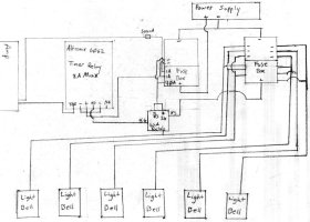
Basically, the setup is simple. You'll need a metal enclosure or cabinet or something to put the relay in. When it's mounted, hook the 12v 500mA power supply to the positive and negative terminals on the Altronix 6062 Multi-Function Timer. Then, take the midi cable and cut it. We're going to make our trigger wire to the amp now. Plug the end that's still normal into the amp charger, and take the cut end and strip it down. We'll be using the Shield and the Red wires here. All other wires can get taped up. Go ahead and put a heatshrink protector on the shield wire since it's bare. Just leave a little wire exposed on him at the end and go ahead and connect that to the TRG input on the timer. Take the red wire, strip him and connect him to the + terminal on the relay board along with the + 12v power. 

Next, for the wiring of the lights. Pretty simple. Run all your fire alarm wire to your lights or whatever you're powering to turn on with this, and bring it back to the enclosure your relay is in. Take your ground wire and connect him to the ground of your 12vDC 2.5A power supply. (By the way....don't use the 2.5A power supply on the relay/amp hookup accidentally...you'll blow up the tiny relay in the amp) Then, take the positive lead going to your lights and connect him to your NO terminal on your relay board. Take the positive lead on the power supply and connect him to the C terminal.

You're all done wiring. Now to program the relay...follow the directions to make sure your timer wheel is set correctly. Make sure the dipswitches are set as follows: 

DIP1: OFF

DIP2: OFF for minutes ON for seconds

DIP3: ON for 12v

DIP4: OFF

Cut Jumper 3 if you don't want the system to alarm when there is a power outage.

I hope this helps. If you want, I can be more detailed. Post any questions below that you have. I should be more responsive now.

Stay disciplined. Max.
 
I did basically the same thing at our stations, but the main purpose of ours is to mute the stations radio audio at night and the relays are used to unmute it when we get a call. 

This is my prototype for the new arduino controlled version. It'll be triggered by the "VIP out" functions of our XTL base radios (but could be triggered by a minitor amplified charger just the same).

[Broken External Image]:http://www.wesleychapelvfd.org/temp/IMG_9323-2.jpg
 
I know this is a long time past the last post, but I just found it.


Is there a way to add speakers directly to the system to hear the dispatch? If so, what other equipment, besides speakers, would be necessary?
 
I know this is a long time past the last post, but I just found it.


Is there a way to add speakers directly to the system to hear the dispatch? If so, what other equipment, besides speakers, would be necessary?
Yes, we tied our overhead station speakers into the Minitor V base by just using the AUX port on the back and it works great for us. 
 
(By the way....don't use the 2.5A power supply on the relay/amp hookup accidentally...you'll blow up the tiny relay in the amp)
Question about this. I don't see how this would damage the relay in the amp?
I could only see this damaging the relay in the amp if DC>amp/relay>high draw item ex light. How much amperes does the relay use?

to be safe DC>500mA fuse>amp/relay/ ext relay.

The reason i'm asking, I'd like to use one power supply.
 
The relay inside the amplified charger is very small. You really should use a separate power supply, if for no other reason than to prevent feeding the amplified charger's internal relay contacts the voltage spike created by breaking the external relay's coil circuit.

Relay Dry Contact Closure (Pins 2 & 3)
  • When the accessory relay is energized, its contacts
    close and present a short across pins 2 and 3 of the
    connector. The relay contacts are rated for 10 watts,
    maximum at 28 volts dc/ac rms. Within the limits of
    the 10 watt rating, the closed contacts will handle up
    to 750 milliamperes continuously and will switch up to
    400 milliamperes of current.
Source: http://www.batlabs.com/minitor.html
I got ya. This is a rough sketch up. I'll change it if I can find a program to draw it.
216887
 

Forum Statistics

Threads
54,650
Messages
452,615
Members
19,468
Latest member
lightbar startup